The column of a steel hall: how it is sized, how it is anchored and where mistakes are made
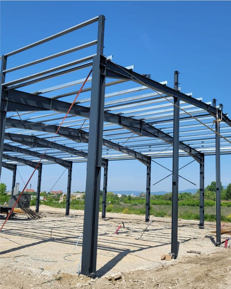
The column of a steel hall almost never fails by the steel being crushed. It fails by suddenly moving out to the side — it buckles — at a force many times smaller than the one the same cross-section would carry if it were short. That is why the question “what size of section do I need” is wrongly put. The real question is: how long is that column between two points that hold it. This text goes through that, through the base plate beneath it, through the anchors that hold it to the concrete and through the mistakes that stop the crane on site.
Why a column buckles before it breaks
Take an IPE 400 in S355 steel. The area of the cross-section is 8,446 mm², so the pure yield limit would come to almost 3,000 kN — some three hundred tonnes. Stand it upright over seven metres, with nothing at its side, and its resistance falls to about 480 kN. You have used 16 % of what you paid for the steel. Fix wall purlins to it every 1.75 m and the resistance jumps to about 2,540 kN — 85 %. The same section, the same steel, the same height.
The standard describes the mechanism without any drama. To HRN EN 1993-1-1, §6.3.1 the resistance of a compression member is Nb,Rd = χ · A · fy / γM1, where χ is the reduction factor that depends on the relative slendernessλ̄ — the ratio of the buckling length to the radius of gyration of the cross-section, divided by the reference slenderness λ1 = 93.9 · √(235/fy). In I-sections the radius of gyration about the weak axis is considerably smaller than about the strong one: an IPE 400 has iy = 165.5 mm, and iz= 39.5 mm. More than four times less. That is why a column always buckles “to the side”, towards the weaker axis — unless someone holds that side.
Buckling resistance of the column
Spacing of the lateral restraints (wall purlins)
Buckling resistance
481 kN
Nb,Rd
If there were no buckling
2,998 kN
A · fy (gross cross-section)
Utilisation of the cross-section
16 %
* What is calculated is the resistance to flexural buckling to HRN EN 1993-1-1, §6.3.1 (expressions 6.47 and 6.49), with γM0 = γM1 = 1.0. This is not a column design: a real column in a frame also carries a bending moment and is verified to §6.3.3 (expressions 6.61 and 6.62), and lateral-torsional buckling is not checked here. The calculation uses the gross cross-section: deeper IPE sections in pure compression fall into cross-section class 4 (slender web), and the standard then calls for the effective area Aeff to expression (6.48), which is a few per cent smaller. The buckling length is taken as the system length, which is also the recommendation for portal frames — the stability of the frame is verified separately, through αcr or a second-order analysis.
A practical rule worth remembering follows from the calculator: wall purlins are not merely a support for the panel. They are a structural element that holds the column, and without which a considerably heavier section would be needed. When someone “saves” in a quotation by thinning out the purlins, the saving on the sheeting is paid for in the steel of the column — only that shows up in the structural calculation, not in the quotation.
Pinned or fixed: the decision the foundation pays for
The second big influence on the section of the column is what happens at its foot. A pinned base transfers only the vertical and the horizontal force to the foundation; a fixed base transfers a moment as well. A fixed base reduces the moment in the rafter and the deflection at the eaves, and so allows a lighter frame — but that moment has to go somewhere, and it goes into the foundation. The result is a larger and deeper pad foundation. A pinned base means a cheaper foundation and more expensive steel. That is the real trade-off in every hall, and in a quotation the client almost never sees it set out separately.
It is also worth knowing that “pinned” does not mean a hinge in practice. A base with four bolts and a base plate is neither an ideal pin nor an ideal fixity. European design practice (the SCI/CTICM guides for portal frames) recommends taking such a base in the global analysis as about 10 % of the stiffness of the column when checking the stability of the frame, and 20 % when calculating deflections. That is a modelling assumption, not a provision of the standard, and it is documented as such in the structural calculation. The criteria for when a base may be treated as rigid at all are given by HRN EN 1993-1-8, §5.2.2.5.
In addition, HRN EN 1993-1-1 gives no table of buckling length factors (the 0.5 / 0.7 / 1.0 / 2.0 from the textbook) for frames. Those factors apply to the idealised boundary conditions of a single member, not to a portal frame. In a frame the system length of the column is taken in the plane, and the stability of the whole is verified through the factor αcr: to §5.2.1(3) second-order effects may only be neglected if αcr ≥ 10 in an elastic analysis, or ≥ 15 in a plastic one. Below that, the calculation follows second-order theory.
Why a column is usually not an IPE
There are two reasons, both measurable. The first is precisely the radius of gyration: HEA and HEB sections are as wide as they are deep, so their iz is much closer to iy — an HEB 300 has 129.9 and 75.8 mm, while an IPE 400 has 165.5 and 39.5 mm. In pure compression without lateral restraint the HEB is therefore far more efficient.
The second reason is subtler and shows up in the buckling curve. To Table 6.2 of the standard, a rolled I-section with an h/b ratio greater than 1.2 is given curve a about the strong axis and b about the weak one; a section with h/b ≤ 1.2 — and those are the lower HE sections, roughly up to HEA/HEB 300 — is given b and c. (Deeper HE sections come back over the limit of 1.2 and are given a and b again.) At first sight that favours the IPE, but the figure that decides is the slenderness, not the curve: the small izof the IPE drives λ̄ so high that even the better curve does not help it. The calculator above shows that in a second if you switch from IPE 400 to HEB 300 at seven metres without restraint.
With portal frames, where the column carries a substantial moment alongside the compression, the picture changes: the column and the rafter are then often chosen from the same family of sections, and for large spans a welded I-section of varying depth is used — deeper where the moment is greatest, shallower at the foot. For great heights and spans the alternative is a lattice column, which efficiently spreads the material far from the axis. Which of those approaches is cheaper is not decided by a rule but by the calculation, because welding and erection move the cost that was saved in the mass of steel.
The base plate: its thickness follows from the concrete beneath it
This is the part most people picture wrongly. A base plate does not work on the principle that “the wider it is, the better it spreads the load”. To HRN EN 1993-1-8, §6.2.5 the plate is modelled as an equivalent T-stub: around the cross-section of the column there is a strip of width c that actually transfers the pressure into the concrete, and everything outside that strip is neglected in the calculation. That width follows from equating the bending moment of a cantilever of span c with the plastic moment of the plate itself:
Turned round, that means: a thicker plate gives a wider load-bearing strip, a wider plate gives nothing. And second, perhaps more important for the client: in the denominator stands fjd, the design strength of the joint, which depends directly on the concrete class of the foundation. Weaker concrete calls for a thicker steel plate. A saving on the class of concrete comes back as a cost in steel, and plates of 25 or 30 mm are cheap neither to cut nor to drill.
Then there is the grout, which is treated on site as cosmetics but is a load-bearing element in the calculation. The joint coefficient βj = 2/3 from §6.2.5(7) may only be used if the grout has at least 0.2 × the strength of the foundation concrete and if the layer is no thicker than 0.2 × the smallest width of the base plate. If the thickness of the grout exceeds 50 mm, the grout must be of at least the same strength as the foundation concrete. If those conditions are not met, the grout is verified separately, as is the concrete block. Grout that has not been placed, or has been placed only in part, means that the column stands on a few points instead of on distributed pressure — and that is not what the designer calculated.
Anchors: a world of their own beside the rest of the structure
Few people know that the anchoring is not covered by the CE marking of the steel structure. The standard HRN EN 1090-1, to which the structure is CE-marked, expressly excludes anchor bolts, anchor plates and elements cast into concrete from its scope. HRN EN 1090-2 does prescribe their installation and their tolerances — but not their design. The design of fastenings in concrete is covered by a separate standard — HRN EN 1992-4:2018 — which brought together the earlier series of technical specifications and covers cast-in anchors, anchor channels, post-installed mechanical and chemical anchors, including fatigue and seismic actions and fire. The practical consequence: when you ask for documentation, the certificate of the structure and the verification of the anchoring are two separate papers. What the certificate of the structure covers we wrote about in the article on EXC classes.
Why are post-drilled anchors avoided on halls, even though they are quicker? It is not a matter of the standard but of the physics of the model. Drilling into a pad foundation cuts through the reinforcement precisely in the tension zone that is the most heavily loaded with a fixed base. A post-installed anchor carries through bond or friction, so concrete cone failure is often governing rather than the steel of the bolt — and that at the small edge distances that are exactly what you have at the edge of a foundation. The concrete of the foundation is cracked in service, and resistances in cracked concrete are considerably lower and call for an anchor with the appropriate assessment. And finally: a cast-in anchor with a plate or a hook has a mechanical anchorage, while a chemical anchor depends on how honestly the hole was cleaned on site, at what temperature, and how long it waited before being loaded.
Tolerances: three millimetres or ten, and why that is a design decision
The anchor tolerance is not one figure but two, and the difference between them is a design decision taken months before anyone goes out on site. HRN EN 1090-2, Table B.23 distinguishes the rigidly cast-in anchor, with no possibility of movement, for which a positional deviation of ±3 mm is permitted, and the anchor prepared for adjustment — in a sleeve or a pocket — for which ±10 mm is permitted. A threefold difference, and that is the only reason anchors are set in sleeves at all.
Alongside the position, the same table separately tolerates the position of the centre of the group of anchors (6 mm) — because the column does not care where an individual bolt sits but where the group as a whole is — and the protruding length of the bolt, where the deviation upwards is generous (+25 or +45 mm) and downwards almost nothing (−5 mm): a bolt that is too short cannot be put right. The level of the foundation is tolerated asymmetrically, −15 mm downwards, but only +5 mm upwards, because a shortfall is made up with grout while an excess means chiselling.
A small thing that gives away out-of-date documentation: in the 2008 edition of the standard the erection tolerances were in Annex D, which is why older bills of quantities cite “D.2.20”. In the 2018 edition they moved to Annex B. If you see a reference to Annex D in a quotation, you are looking at text copied from a guide more than a decade old.
For the column itself, after erection the governing figure is the inclination. For an ordinary column of a single-storey hall the basic tolerance is h/300 — at seven metres that is some twenty millimetres. For a column that carries a crane runway the tolerance is h/1000, that is seven millimetres at the same height. The same works, the same crew, a measure more than three times stricter. (The standard also separately tolerates the mean inclination of all the columns of the same frame, more strictly than the individual one — the frame as a whole must stand upright even if an individual column is allowed to deviate more.)
Seven mistakes that stop the erection
- Erection begun before the supports were handed over. The standard requires the position and the levels of the supports to be checked by measurement and non-conformities to be put right before erection begins — not to be dealt with when the crane is already on site.
- Grouting before alignment. The grout is not placed until the structure has been aligned, levelled and braced. Grout earlier and you have cast the error in concrete.
- Grout brought up above the underside of the plate, with no fall. Water then stays in the joint between the steel and the concrete. The standard requires the profile of the grout to lead water away from the steel.
- Shims left uncovered. If they stay in place, they must be completely enclosed by the grout and of a material of equal durability — otherwise they are a corrosion bridge right under the column.
- Anchors used to secure an unbraced column against overturning. The standard allows that only if they have been expressly verified for that situation. The temporary bracing stays until erection has progressed far enough.
- A connection counted as stabilising with too few bolts fitted. The standard recommends that at least a third of the permanent bolts be in place before that connection may be treated as a contribution to the stability of a partly erected structure.
- A preloaded anchor bolt grouted over its whole length. If the bolt is preloaded, its upper part must have no bond with the concrete — otherwise it has no free length over which to stretch.
“We will add the crane later” — the most expensive sentence in the project
An overhead travelling crane changes the column in three ways at once. First, it introduces lateral and longitudinal forces from acceleration and braking, with dynamic factors — those actions are laid down by a separate standard, HRN EN 1991-3. Second, the loading becomes repeated, so the structure must also be verified for fatigue, to HRN EN 1993-1-9, and crane runways have their own standard, HRN EN 1993-6. Third, the tolerance on the inclination of the column falls from h/300 to h/1000.
That is why adding a crane runway to an existing hall afterwards is almost never “just hanging up a beam”. The calculation of the column changes, often the foundation too, and the structure moves into a stricter execution class. If you are thinking of a crane even in the slightest, it is cheaper to say so to the designer at the start than to strengthen the hall later.
The base of the column is the most critical place for corrosion
There is a widespread assumption that the inside of a hall is milder than the outside. Not necessarily. EN ISO 12944-2 classifies the environment by corrosivity category, and on that division an unheated warehouse in which condensation occurs is C2, while a production plant with moisture — a dairy, a laundry, the food industry — is C3. A swimming pool or a chemical plant is C4, and a space with almost permanent condensation and high pollution is C5. Outdoors, rural Slavonia is C2 and an industrial zone C3. In other words, the inside of a hall not infrequently carries a stricter category than its outside — and the coating system is chosen by category.
Within that, the base of the column is the most exposed point. EN ISO 12944-3, which deals with the design of the structure with regard to corrosion, expressly calls in its part on gaps and crevices for particular attention at transitions from concrete to steel: narrow gaps hold moisture and dirt and are a typical point of attack, so they are sealed. Alongside that, it calls for avoiding surfaces on which water stands and for leading water away from the structure — which is exactly what the rule on the profile of the grout requires as well.
For a comparison of durability: a hot-dip galvanised coating of about 85 µm mean thickness (as much as EN ISO 1461 requires for steel thicker than 6 mm) lasts decades in C2 and C3, but by the corrosion rates for zinc from EN ISO 14713-1 it falls in C4 to the order of 20 to 40 years, and in C5 to 10 to 20. In a damp plant, then, galvanising alone is not a “solution for life” but the beginning of a coating system, not its end.
What to ask before signing
- Is the base of the column pinned or fixed, and is the foundation sized for the moment that comes out of it?
- Are the anchors cast in or in sleeves — so do ±3 or ±10 mm apply to them?
- Who supplies the grout, of what strength, and who places it — is that within the scope of the steel supply or of the building contractor?
- Which corrosivity category was taken for the inside and which for the outside, and for what durability was the coating system designed?
- Is the column laterally restrained by wall purlins, and at what spacing — that is the figure that determines its section?
The column is the most modest part of a hall: it is not seen, it is not sold and nobody boasts of it. But almost every decision taken on it — how well it is restrained, how it stands on the foundation and how it is protected at the bottom — will show only in ten or twenty years, and then it can no longer be put right cheaply. More on execution classes and the documentation you are entitled to ask for is in the article on HRN EN 1090-2, and we set out the whole road from the enquiry to the occupancy permit in the guide to prefabricated halls. The anchor tolerances from Table B.23 are only one link — how all the deviations add up to the envelope we set out in the article on erection tolerances.
We make steel structures and prefabricated halls in our own production in Đakovo. If you have the overall dimensions, the intended use and the information on whether there will be a crane in the hall, we can start from that — about steel structures and an enquiry with dimensions.
Frequently asked questions
The resistance of a compression member depends on its slenderness and not only on the area of the cross-section. An IPE 400 in S355 over seven metres without lateral restraint carries about 480 kN, although the pure yield limit would be almost 3,000 kN.
English version of the Croatian original: Stup čelične hale: kako se dimenzionira, kako se sidri i gdje se griješi.